Description
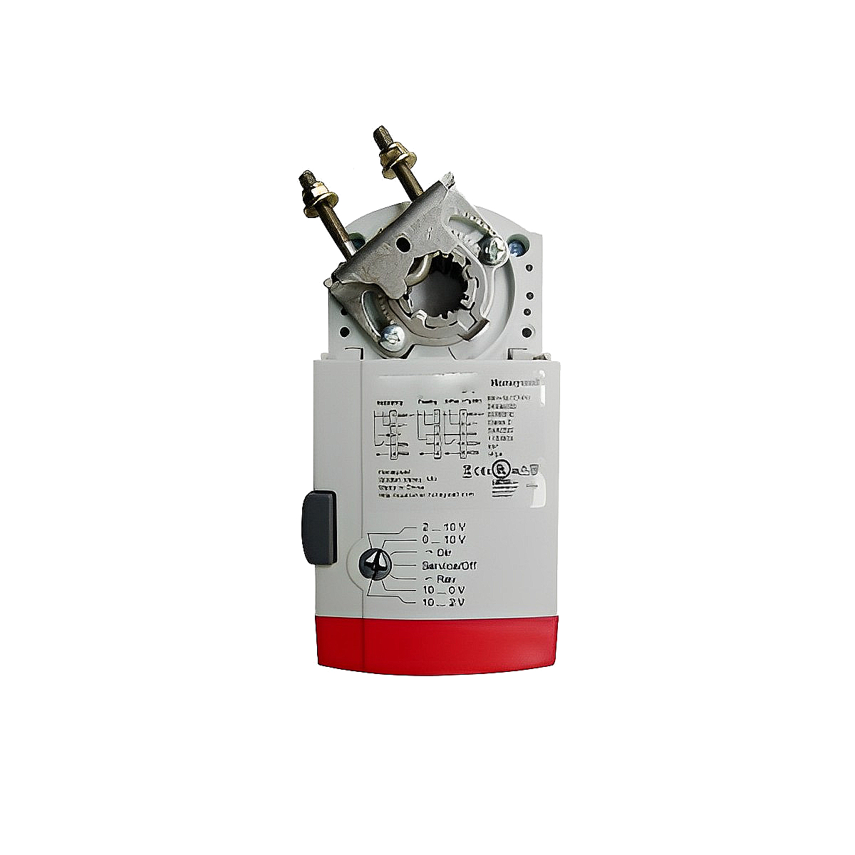
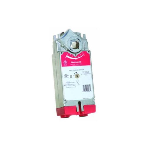
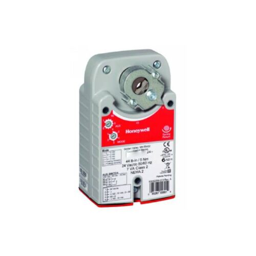
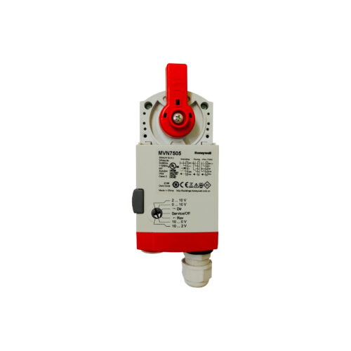
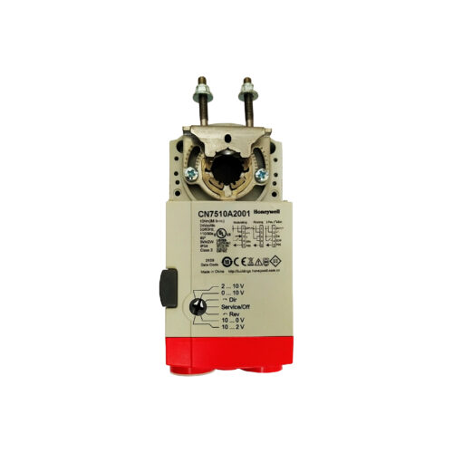
CN7510A2209 Honeywell Damper Actuator , NON-SPRING RETURN DIRECT-COUPLED DAMPER ACTUATORS FOR MODULATING AND FLOATING CONTROL
This non-spring return direct-coupled damper actuator provides modulating and floating/2 position control for:
- air dampers,
- VAV units,
- air handlers,
- ventilation flaps,
- louvers, and
- reliable control for air damper applications with up to 10 sq.ft. / 44 lb-in. (5 Nm) and 20 sq.ft. / 88 lb-in. (10 Nm) (seal- less damper blades; air friction dependent).
Features of Honeywell Damper Actuator CN7510A2209 :
- Declutch for manual adjustment
- Adjustable mechanical end limits
- Removable access cover for direct wiring
- Mountable in any orientation
- Function selection switch for selecting modulating or floating/2-position control
RUN MODES
You can use the function selection switch to place the actuator into any one of two different modes.
- Service/Off
- Floating/2-Position Run Mode
- Modulating Run Mode
Service/Off
If you set the function selection switch to the “Service/Off” position, it will cancel all rotary movement and ignore all control signals, allowing you to manually operate the actuator safely.
Floating/2-Position Run Mode
Without Feedback Signal
In the event that the function selection switch is set to one of the two floating/2-position control settings, but the actuator has not been wired for a feedback signal, the shaft adapter will run based on the control signals applied immediately upon applying the operating power.
With Feedback Signal
Assuming you have set the function selection switch to one of the four modulating control settings and wired the actuator accordingly, the shaft adapter will initiate by running completely counterclockwise and then completely clockwise as soon as you apply operating power. Once this initialization process has completed, it will operate based on the control signals applied.
Modulating Run Mode
Provided that you have set the function selection switch to one of the four modulating control settings and wired the actuator accordingly, the shaft adapter will commence by running completely counterclockwise, followed by running completely clockwise as soon as operating power is applied. Once this initialization process has been completed, the shaft adapter will operate based on the control signals applied.


Reviews
There are no reviews yet.